On my previous post on the hazard light subject I was enquiring if there was an updated wiring diagram for post '74 vehicles. Well behold there is! MR510-60a. Thanks to Chris at aussiefrogs.
The wiring diagram answered my dilemma about the problem of feeding a permanent or accessory live to the flasher unit. The problems were if (1) you supplied the flasher unit with a permanent live – you could inadvertently leave your indicators flashing and (2) if you supplied the flasher unit with a ignition live – you could not use the hazards with the ignition switched off.
Citroëns answer? Use 2 flasher units one for the indicators and a second for the hazards. (If only I'd thought of that?)
The thread at aussiefrogs can be read here, and the diagrams can be downloaded (in French) from the previous blog - enjoy.
Friday, 14 April 2017

Friday, 7 April 2017
Hazard lights
Post 1974 Model Year DS' were fitted with hazard lights as standard, as this was shortly before the end of production there was no updated wiring or layout diagrams available (unless you know otherwise?) I have produced my own wiring diagrams which are loosely based on the original but simplified for ease of use.
There are various ways of making the existing flasher unit operate all four indicators with the use of a relay(s) but with the use of a correct switch there is no need for additional relays.
This is my solution.
The original flasher unit operation relied on a bi-metal strip heating up and breaking/making a connection, the speed of this depended on the battery state, wiring connections, good earths, bulb condition, etc. Adding an additional two indicators and a warning lamp will change the speed again. The solution is to replace the old flasher unit with an electronic three pin flasher unit which will flash at a constant speed in all conditions.
Original 74MY switches are not readily available, I was lucky to find one for sale in Holland at ICCCR2016, it matches the existing dash switches and has four arrows on it depicting all four indicators. Other switches are available; the seven pin 2CV switch doesn’t look out of place and are available from ECAS or Burton, other ‘period’ switches also look good. Therefore I will be describing two options; the astonishingly simple DS option (4 pin) and the 2CV option (7pin)
The parts you will need;
• Hazard switch
• 3 pin electronic flasher unit
• Coloured wires (yellow, brown, green, red and black)
• Dash warning lamp and holder
• Spade connectors and insulators
First and foremost DISCONECT THE BATTERY you don’t want any sparks, burnt fingers or melted wiring. Don’t say I didn’t warn you.
You will need access to the flasher unit and indicator switch by removing the dash binnacle. Replace the flasher unit as per wiring diagram and using a black wire add an additional earth to pin 31.
Next you will need to fit your hazard switch, where you fit this is up to you. The original one fitted in the metal part of the dash next to the choke cable (carb.model), if you don’t fancy cutting the metal part of the dash use the plastic facia panel that houses the other switches; I think that’s close enough. The aperture required is 30mm. x 20mm.
How the switch works. (DS option) This has one feed in from the flasher unit and three feeds out to LH indicator, RH indicator and warning lamp. Told you it was simple.
(2CV option) The switch is basically two sets of contacts joined by the action of the push button. Set 1, this redirects the ignition live to a permanent live so you can use the hazards without the ignition being switched on. Set 2, this has one feed in from the flasher unit and three feeds out to LH indicator, RH indicator and warning lamp as per the DS option. The good thing about this layout is (a) your hazard lights will operate with the ignition off and (b) you won’t leave your indicators flashing all night by mistake.
Wiring the hazard switch depends on your switch, unless you have the switch diagram you will have to use a meter to establish which contact does what. If you only have a six pin switch you will have to use a four pin flasher unit for the warning lamp (I will come back to this later)
Either way the principle is the same,
2CV option; (Set 1) the original yellow wire from F3 goes to the normally closed (NC) contact and the common contact now goes to pin 49 of the new flasher unit. This will allow normal operation of the direction indicators with the ignition on and a new permanent feed from F5 which supplies the normally open (NO) feed for the hazard lights, you can alternatively us a feed from the +ve accessory post. Next (Set 2) supply the common (NO) contacts with a red wire which connects to either the red wire on the indicator switch or pin 49a on the new flasher unit whichever is the easiest, this will feed all four indicators and the dash warning lamp when activated. The (NO) contacts feed the indicators via a new green and yellow wire which are spliced into the existing wiring from the indicator switch. Finally the last feed is for the dash warning lamp.
DS option; as per Set2 on the 2CV option.
On the white plug that connects onto the dash binnacle there is a spare connection in the middle row this supplies the feed to the hazard warning lamp, connect a black wire to this from the switch and fit a new lamp holder at the very lower blank space in the binnacle (Hold it up to the light and you will see a red lens with the four arrows on it) The earth for the warning lamp is already in place. Reconnect the battery, rebuild your dash binnacle and test your new hazard lights.
If you only have a six pin switch you will have to use a four pin flasher unit for the warning lamp, the last feed for the warning lamp comes from the fourth pin on the flasher unit (marked C)
Last thing, you will be drawing extra load on the indicator circuit with the hazards lights switched on, so if you find yourself blowing a fuse just up the rating by 4 Amps for the additional 2x21W and 4W bulbs.
Wiring diagrams can be found here, feel free to download.
https://drive.google.com/open?id=0ByRsL7HMnnc5alNxRF9XZ19yMGc
There are various ways of making the existing flasher unit operate all four indicators with the use of a relay(s) but with the use of a correct switch there is no need for additional relays.
This is my solution.
The original flasher unit operation relied on a bi-metal strip heating up and breaking/making a connection, the speed of this depended on the battery state, wiring connections, good earths, bulb condition, etc. Adding an additional two indicators and a warning lamp will change the speed again. The solution is to replace the old flasher unit with an electronic three pin flasher unit which will flash at a constant speed in all conditions.
Original 74MY switches are not readily available, I was lucky to find one for sale in Holland at ICCCR2016, it matches the existing dash switches and has four arrows on it depicting all four indicators. Other switches are available; the seven pin 2CV switch doesn’t look out of place and are available from ECAS or Burton, other ‘period’ switches also look good. Therefore I will be describing two options; the astonishingly simple DS option (4 pin) and the 2CV option (7pin)
The parts you will need;
• Hazard switch
• 3 pin electronic flasher unit
• Coloured wires (yellow, brown, green, red and black)
• Dash warning lamp and holder
• Spade connectors and insulators
First and foremost DISCONECT THE BATTERY you don’t want any sparks, burnt fingers or melted wiring. Don’t say I didn’t warn you.
You will need access to the flasher unit and indicator switch by removing the dash binnacle. Replace the flasher unit as per wiring diagram and using a black wire add an additional earth to pin 31.
Next you will need to fit your hazard switch, where you fit this is up to you. The original one fitted in the metal part of the dash next to the choke cable (carb.model), if you don’t fancy cutting the metal part of the dash use the plastic facia panel that houses the other switches; I think that’s close enough. The aperture required is 30mm. x 20mm.
How the switch works. (DS option) This has one feed in from the flasher unit and three feeds out to LH indicator, RH indicator and warning lamp. Told you it was simple.
(2CV option) The switch is basically two sets of contacts joined by the action of the push button. Set 1, this redirects the ignition live to a permanent live so you can use the hazards without the ignition being switched on. Set 2, this has one feed in from the flasher unit and three feeds out to LH indicator, RH indicator and warning lamp as per the DS option. The good thing about this layout is (a) your hazard lights will operate with the ignition off and (b) you won’t leave your indicators flashing all night by mistake.
Wiring the hazard switch depends on your switch, unless you have the switch diagram you will have to use a meter to establish which contact does what. If you only have a six pin switch you will have to use a four pin flasher unit for the warning lamp (I will come back to this later)
Either way the principle is the same,
2CV option; (Set 1) the original yellow wire from F3 goes to the normally closed (NC) contact and the common contact now goes to pin 49 of the new flasher unit. This will allow normal operation of the direction indicators with the ignition on and a new permanent feed from F5 which supplies the normally open (NO) feed for the hazard lights, you can alternatively us a feed from the +ve accessory post. Next (Set 2) supply the common (NO) contacts with a red wire which connects to either the red wire on the indicator switch or pin 49a on the new flasher unit whichever is the easiest, this will feed all four indicators and the dash warning lamp when activated. The (NO) contacts feed the indicators via a new green and yellow wire which are spliced into the existing wiring from the indicator switch. Finally the last feed is for the dash warning lamp.
DS option; as per Set2 on the 2CV option.
On the white plug that connects onto the dash binnacle there is a spare connection in the middle row this supplies the feed to the hazard warning lamp, connect a black wire to this from the switch and fit a new lamp holder at the very lower blank space in the binnacle (Hold it up to the light and you will see a red lens with the four arrows on it) The earth for the warning lamp is already in place. Reconnect the battery, rebuild your dash binnacle and test your new hazard lights.
If you only have a six pin switch you will have to use a four pin flasher unit for the warning lamp, the last feed for the warning lamp comes from the fourth pin on the flasher unit (marked C)
Last thing, you will be drawing extra load on the indicator circuit with the hazards lights switched on, so if you find yourself blowing a fuse just up the rating by 4 Amps for the additional 2x21W and 4W bulbs.
Wiring diagrams can be found here, feel free to download.
https://drive.google.com/open?id=0ByRsL7HMnnc5alNxRF9XZ19yMGc
 |
| Front of original DS hazard switch |
 | |||
| Rear of switch |
 |
| Rear of switch showing colour coding for wiring |
 |
| 2CV switch (courtesy of Burton) |
 |
| 2CV switch (courtesy of ECAS) |
 |
| 3 pin electronic flasher relay (courtesy of vehicle wiring products) |
 |
| 4 pin electronic flasher relay showing pin C for warning lamp (courtesy of vehicle wiring products) |
 |
| This is the section of the metal part of the dashboard where the hazard switch should fit |
 |
| Here we have an alternative position with the easier to cut plastic facia panel |
 |
| At the rear of the warning lamp lens cluster showing the hazard lamp position (courtesy of aussiefrogs) |
Friday, 13 January 2017
Zinc plating
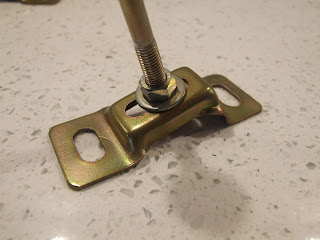
The Winter months are fruitless in a cold garage so not much progress going on here. However a little bit of zinc plating is always fun to do, not only does it make components look good it provides suitable rust prevention. Some components have received a yellow passivate as original.




 |
| Anyone know what these are? |
 |
| Center arm rest before... |
 |
| ...and after |
Friday, 23 December 2016
Another year nearly over
Just returned from Germany for Christmas so I would like to wish all my readers a very Merry Christmas and a Happy New Year for 2017.
Please subscribe to receive regular updates there will be a lot going on next year.
Please subscribe to receive regular updates there will be a lot going on next year.
 |
| I know it's a 2CV...but it's all I could find! |
Monday, 26 September 2016
Carpets
The carpets I bought at ICCCR in Holland have to start going in the car sooner rather than later. I didn't want to leave it too late and come across a problem which couldn't be resolved. Having said all that, the carpets are of great quality and good progress is being made. The original soundproofing/underlay is in good condition and is being re-used.
 |
| Original carpet... well rotted |
 |
| New carpet section with original foam being used |
 |
| This is the section that is fitted underneath the front seats with runners in place |
The piece shown at the bottom of the photo is the original section for the rear foot-well and serves as a good comparison of the colour and quality match.
 |
| Front ¼ panel |
These small pieces on the front ¼ panels are more involved than at first sight. A slot has to cut into the carpet to accommodate the welded bracket and then you have to figure out how to remove the bonnet release.
 |
| Front bulkhead |
To install the front bulkhead carpet the heater control panel had to be removed, the red section is notorious for fading away. A bit of careful masking and my daughters red nail varnish makes it look a lot better. You can buy stickers for these but are expensive at about £20.00.
 |
| 2mm foam strip fills the gap formed by the reinforcing plate on the inner sill |
 |
| Trim piece for brake pedal |
Refitting the trim piece for the brake pedal is a tricky job, there are 6 small bolts securing it to the support for the pedal gear and into the floor.
Naturally nothing lines up properly.
Naturally nothing lines up properly.


Thursday, 8 September 2016
Rear bumper woes :(
Now here's a lesson learned in how not to check the ‘softness’
of your Citroën DS suspension! Use something solid to kneel on like the rear panel of the
boot and NOT the top section of the rear bumper; they are a great deal more delicate
than they first appear.
So after much cursing I decided to remove the bumper to see if could be straightened. After removing the bumper it revealed a few more problems, namely the bumper support brackets were badly corroded, the support rubbers were worn and the rear lights were misaligned, these additional jobs would be sorted while the bumper was off.
eBay to the rescue which sourced a quite good top bumper section, the original was far too damaged to be repaired, The part was in Holland at a price of £35.00 and had a small dent which was repairable.
Note to self;
Well worth the effort as it now looks much better that it did originally but don't kneel on the rear bumper again.
 |
| Rear bumper damage after kneeling on it! |
 |
| Corroded rear bumper bracket |
 |
| Rear bumper removed, back panel re-painted and wiring connectors cleaned and greased |
 |
| Rear light panel had seen better days, a good clean up and repainted gloss black |
 |
| Rear light panel repainted gloss black |
 |
| New bumper brackets painted and waxoiled, these should last another 40 years |
 |
| Rear light panel refitted with number plate and rear lights that are now straight |
 |
| Checking the rear lights all work |
 |
| Trial fit of the new bumper section |
 |
| All refitted and polished up and all new stainless steel fittings were used as the old mild steel bolts had to be cut off. |
Well worth the effort as it now looks much better that it did originally but don't kneel on the rear bumper again.
Thursday, 28 July 2016
ICCCR2016... Come and say Hello!
Anyone in Holland in a few weeks time? Come and say Hello, it would be nice to put a face to a username or email address. I will be in the camping area in the white C5 Tourer with this flag flying... bring a bottle if you like ;)
 |
| See you in Holland! |
Subscribe to:
Posts (Atom)